

Panel Lab · Level 7 of 10
Commission the variable-speed infeed conveyor drive
Level 7 of 10 in the Panel Lab: a free panel wiring exercise at Advanced level. Wire a variable frequency drive: mains in and motor out, two-channel safe torque off from the E-STOP, run commands from the PLC, a 0 to 10 V speed reference and a fault relay.
Free · no download. Your work is saved on this device. Updated 18 Oct 2026.
The brief
- Work order
- WO-PS-701
- Job
- Commission the variable-speed infeed conveyor drive
- Difficulty
- Advanced
- Type of work
- Commissioning
- Detail
- 33 wires, lockout, meter checks and a PLC program
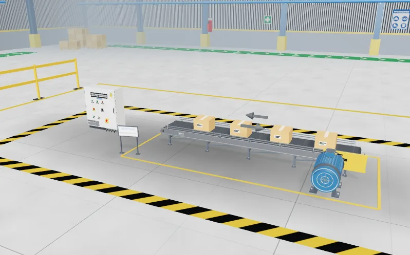
Harbour Spice Co.. Infeed conveyor IC-701 (motor 1.5 kW, 415 V, 3.6 A) needs an adjustable speed from a potentiometer on the door, with FWD and REV buttons through the PLC. The drive V1 (2.2 kW) is mounted in the panel with its settings loaded: 3 s up, 4 s down, 0 to 10 V on AI1, safe torque off enabled. The panel +D701 has arrived with the supply to F2, the 24 V supply and the PLC supply wired. The drive wiring is yours.
What you do
- Lock out the panel at the main isolator Q1: switch OFF, apply your lock and your tag.
- Prove it dead with the meter, live-dead-live. Include the drive's DC bus test points DC+ and DC-: on a real drive the capacitors stay charged for minutes after switch-off, so read the discharge time on the drive's plate and measure before you touch.
- Wire the 33 conductors of the wiring schedule. Power first: F2 goes to the drive's L1 L2 L3 and the motor comes off U V W, never the other way round. Protective earth to both PE terminals. The drive's own earth leakage is high, so the earth connection is fixed and sound.
- There is no contactor in the motor cable, by design. A normal stop is the run command going away so that the drive ramps down. The E-STOP removes torque through STO1 (S2 11-12) and STO2 (S2 21-22): two separate channels.
- The PLC gives run forward (DI1) and run reverse (DI2). The speed is not in the program: RV1 gives the drive 0 to 10 V on AI1 (10V → RV1 3, RV1 2 → AI1, RV1 1 → AGND). The drive's fault relay goes to I0.4.
- Restore power: tick the checklist, remove your tag and lock, switch Q1 ON, put the PLC in RUN.
- Test: set the speed with RV1, run FWD and REV, STOP, the E-STOP and a drive fault (use TEST on the drive, then RESET). Then run the FAT.
What the test checks
The factory acceptance test is marked against the panel you built. The level sets out:
- 33 conductors in the wiring schedule
- 7 dead checks before you touch the panel
In this lab
- Lock out and prove dead, live-dead-live
- Wire the backplate from the schematic
- Meter, tester, clamp and insulation tester
Levels in the Panel Lab
Previous: Commission the sorting station sensorsNext: Commission the 4-20 mA level loop
- Commission the transfer-pump starter
- Fault-find the outfeed conveyor starter
- Commission the star-delta fan starter
- Commission the reversing conveyor starter
- Commission the overhead tank pump (Hand/Off/Auto)
- Commission the sorting station sensors
- Commission the variable-speed infeed conveyor drive
- Commission the 4-20 mA level loop
- Commission the pneumatic pusher station
- Commission the packing cell (capstone)
Part of the Panel Lab
Lock out, wire, test and fault-find a control panel, then prove it with a factory acceptance test.
Feeds these internships: Control Panel Design and Wiring, Commissioning and Maintenance, Instrumentation and Process Control.